Introduction#
Inspired by the legendary MOS6581 Sound Interface Device** (SID) chip used in retro computers such as the Commodore 64, the Tiny Tapeout 6581 (TT6581) is a original digital interpretation supporting nearly the entire original MOS6581 feature set, implemented in 2x2 tiles for Tiny Tapeout.
The goal of this project was to design an original, purely digital audio synthesizer chip that mimics the MOS6581 feature set as best as possible. Other than a few exceptions, the only reference for this project has been the MOS6581 datasheet.
Features:
- Full control through a Serial-Peripheral Interface (SPI).
- Three independently synthesized voices.
- Four supported waveform types (triangle, sawtooth, square and noise).
- Attack, decay, sustain, release (ADSR) envelope shaping.
- Chamberlin State-Variable Filter (SVF) for low-pass, high-pass, band-pass and band-reject.
- Second-order Delta-Sigma DAC.
To demonstrate the chip’s capabilities, here is Rob Hubbard’s Monty on the Run. The track was played using a Verilator RTL testbench, and the final audio was produced by capturing the PDM output and processing it through a 4th-order Bessel filter in Python.
Architecture Overview#
The diagram below shows the datapath in the TT6581. A tick generator divides the 50 MHz system clock by 1,000 to produce a 50 kHz sample tick that triggers the generation of a single audio sample.

The synthesis pipeline processes one sample per tick through six stages:
Voice Generation: One 10-bit voice at a time is generated from a 19-bit phase accumulator. Internal phase registers maintain each voice’s state while inactive. Supported waveforms are triangle, sawtooth, pulse, and noise.
Envelope: An ADSR envelope generator produces an 8-bit amplitude value per voice. The envelope is applied to each voice by multiplication.
Wave Accumulation: The three envelope-scaled voices are accumulated (mixed) by addition. Depending on each voice’s filter-enable bit, the signal is routed into one of two accumulators: one for the SVF input, one for the bypass path.
State-Variable Filter: A Chamberlin SVF processes the filter accumulator. It supports low-pass, high-pass, band-pass, and band-reject modes with tuneable cutoff frequency and resonance (Q).
Global Volume: The SVF output is summed with the bypass accumulator and a global 8-bit volume is applied by multiplication.
Delta-Sigma PDM: A second-order error-feedback delta-sigma modulator converts the final 14-bit mix to a 1-bit PDM output at 10 MHz (OSR = 200).
Time-Multiplexed Pipeline#
To meet the rather strict 2x2 tile area constraint, the entire synthesis pipeline is heavily time-multiplexed. Most modules are finite state machines that execute sequentially rather than in parallel. The design uses a single 24×16 signed shift-add multiplier shared across all modules.
A master controller FSM in controller.sv manages the pipeline. Each 50 kHz sample tick triggers the following sequence:
| State | Operation | Multiplier Use |
|---|---|---|
| SYN | Generate waveform for current voice | - |
| ENV_0 | Compute ADSR envelope, multiply with voice 0 | env x voice 0 |
| ACCUM_0 | Accumulate into filter/bypass register | - |
| ENV_1 | Compute ADSR envelope, multiply with voice 1 | env x voice 1 |
| ACCUM_1 | Accumulate into filter/bypass register | - |
| ENV_2 | Compute ADSR envelope, multiply with voice 2 | env x voice 2 |
| ACCUM_2 | Accumulate into filter/bypass register | - |
| FILT | Run SVF, three multiplications | Q x BP, F x HP, F x BP |
| VOL | Apply global volume | vol × mix |
| DONE | Latch output to delta-sigma | - |
The multiplier input is controlled by a 2-bit mux (mult_in_mux):
mult_in_mux | Operand A (24-bit) | Operand B (16-bit) | Purpose |
|---|---|---|---|
00 | Voice waveform | Envelope | Voice x envelope |
01 | SVF internal node | Filter coefficient (F or Q) | Filter computation |
10 | Mixed audio | Volume | Global volume |
This resource-sharing strategy eliminates the need for three separate multipliers, at the cost of serialising the computation across ~150 clock cycles per sample. With a system clock of 50 MHz and a sample rate of 50 kHz, that is well below the 1000 cycles available between sample ticks.s
Waveform Generation#
The multi_voice.sv module generates three voices sequentially, one at a time (managed by the controller). Each voice has a 19-bit phase accumulator and produces a 10-bit signed output [-512, 511].
During sample generation, the phase accumulator of the currently active voice, \( \phi \), is updated by adding with the 16-bit Frequency Control Word (FCW) (coming from the register file):
$$ \phi[n] = \phi[n-1] + \text{FCW} $$The FCW is split across the FREQ_LO and FREQ_HI registers. The phase accumulator wraps naturally at \( 2^{19} \), producing the frequency:
With \( F_s = 50 \) kHz, the maximum representable frequency is:
$$ f_{\max} = \frac{(2^{16}) (50 \text{ kHz})}{2^{19}} = 6250 \text{ Hz} $$This is a bit above the original MOS6581 and perfectly fine for most musical applications.
Waveform Types#
Each voice supports four waveform types, selected by the upper bits of the CONTROL register. By selectively choosing bits from the phase register, the four waveform types can be generated.
Sawtooth
The top 10 bits of the 19-bit phase accumulator are output directly, producing a linearly rising ramp.
saw = phase[18:9];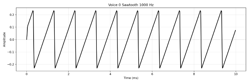
Triangle
A folded version of the sawtooth. The phase MSB determines the fold direction:
tri = phase[18] ? (~phase[17:9] + 10'd1) : phase[17:9];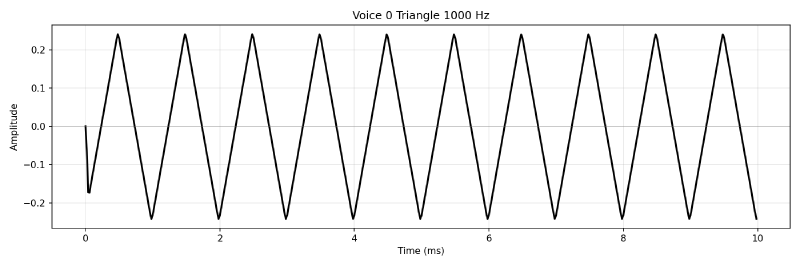
Pulse (Square)
A threshold comparison against the programmable 12-bit pulse width:
pulse = (phase[18:7] >= pw_word) ? 10'h3FF : 10'h000;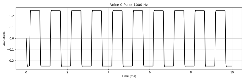
Noise
Generating white noise was a a bit tricky. This implementation is therefore more or less a copy of the MOS6581. A pseudo-random noise generator using a 23-bit linear-feedback shift register (LFSR):
nxt_lfsr = {cur_lfsr[21:0], cur_lfsr[22] ^ cur_lfsr[17]};The LFSR is clocked on the rising edge of bit 18 of the phase accumulator (the same bit that determines the sawtooth period), so the noise “frequency” tracks the programmed FCW. The output is 8 selected bits from the LFSR state:
noise = {lfsr[22], lfsr[20], lfsr[16], lfsr[13],
         lfsr[11], lfsr[7],  lfsr[4],  lfsr[2]};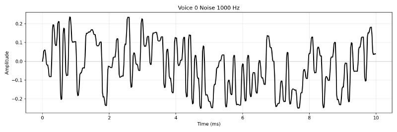
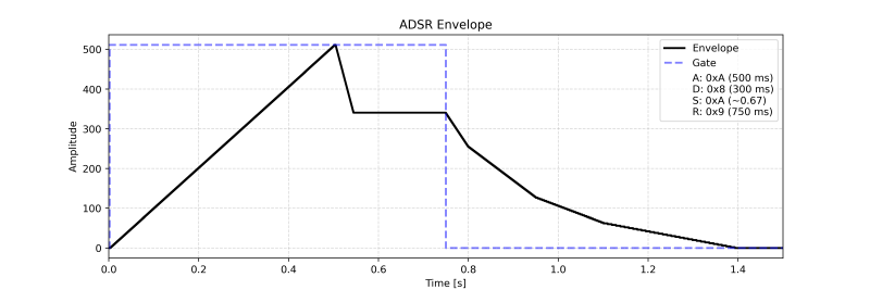
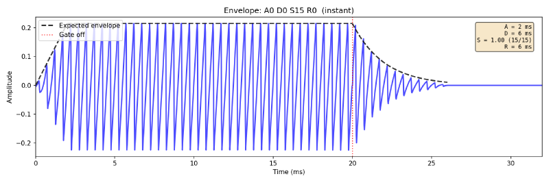
ADSR Envelope Generator#
The envelope.sv module implements per-voice attack-decay-sustain-release (ADSR) envelope shaping. Each voice has an independent 24-bit (Q8.16) volume register that is multiplied with the voice waveform to shape its amplitude over time.
State Machine#
The envelope uses a two-level state machine:
Master FSM (shared across voices, runs once per voice per sample):
| State | Action |
|---|---|
| IDLE | Wait for start signal |
| ADSR | Run the per-voice ADSR state machine |
| MULT | Multiply voice waveform by envelope value |
| DONE | Signal completion |
Per-voice FSM (independent for each voice):
| State | Transition condition | Next State |
|---|---|---|
| ATTACK | Volume reaches 0xFF (max) | DECAY |
| DECAY | Volume falls to sustain level | SUSTAIN |
| SUSTAIN | Hold until gate off | RELEASE |
| RELEASE | Volume reaches zero | RELEASE |
The gate bit in the CONTROL register triggers transitions:
- gate on: ATTACK
- gate off: RELEASE (from any state).
ADSR Cycle#
Attack
During attack, the volume increases by a fixed step per sample tick:
$$ V[n] = V[n-1] + \text{attack\_step} $$The attack step is found in a look-up table indexed by the 4-bit attack rate value. The values match the original MOS6581.
Decay and Release
Decay and release use an exponential decay approximation. Just like the attack rate, the step size is determined by a look-up table and shifted right by an amount (exp_shift) that depends on the current volume:
The exp_shift lookup creates an approximation to exponential decay. When the volume is high, the step is large; as the volume decreases, the step gets progressively smaller.
Sustain
The sustain level is set by the upper 4 bits of the SR register. The volume is held at {sustain, 4'h0, 16'h0} in Q8.16 format until the gate is released.
State-Variable Filter#
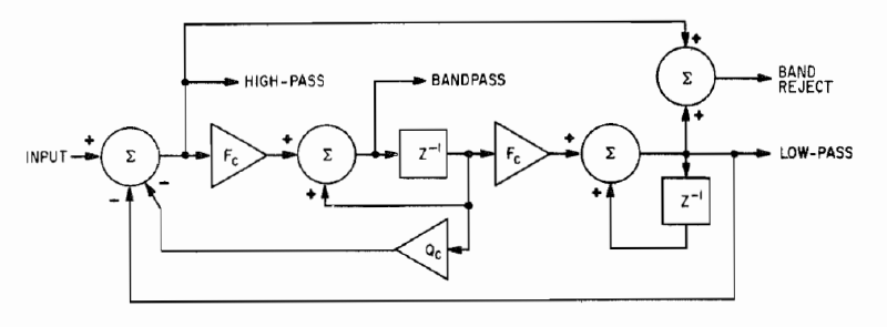
The TT6581 uses a Chamberlin State-Variable Filter (SVF). A second-order digital filter topology originally described in Musical Applications of Microprocessors by Hal Chamberlin. It produces low-pass, high-pass, band-pass and band-reject outputs with tuneable cutoff and resonance (Q).
The SVF supports cutoff frequencies up until ~8000 Hz, after which instability is seen.
Each voice can be independently routed through the filter or bypass it, controlled by bits 5:3 of EN_MODE. Voices routed through the filter are summed into filter_accum; bypassed voices go to bypass_accum. After filtering, both accumulators are summed before the global volume stage.
Filter Equations#
The SVF maintains two state registers (reg_low and reg_band) and computes all four outputs each sample:
HP =  input - LP - Q * BP
BP += F * HP
LP += F * BP
BR = HP + LP
Where:
- F: controls the cutoff frequency (Q1.15 fixed-point)
- Q: controls the damping / resonance (Q4.12 fixed-point)
Hardware Implementation#
The SVF is implemented as a 10-state FSM in svf.sv, requiring three multiplications per sample, all through the shared multiplier:
| State | Operation | Multiplier |
|---|---|---|
| MULT_Q | Compute Q * BP | Q * reg_band |
| WAIT_Q | Wait for multiplier | - |
| CALC_HP | HP = input - LP - Q * BP | - |
| MULT_F1 | Compute F * HP | F * hp_node |
| WAIT_F1 | Wait for multiplier | - |
| CALC_BP | BP += F * HP | - |
| MULT_F2 | Compute F * BP | F * reg_band |
| WAIT_F2 | Wait for multiplier | - |
| CALC_LP | LP += F * BP | - |
| DONE | Latch output, select mode | - |
Coefficient Calculation#
Cutoff Frequency
The cutoff coefficient is a Q1.15 fixed-point value, calculated by:
$$ F = \left\lfloor 2 \cdot \sin\!\left(\frac{\pi \cdot f_c}{F_s}\right) \cdot 32{,}768 \right\rfloor $$Damping Coefficient
The damping coefficient is a Q4.12 fixed-point value, calculated by:
$$ Q_{coeff} = \left\lfloor \frac{1}{Q} \cdot 4{,}096 \right\rfloor $$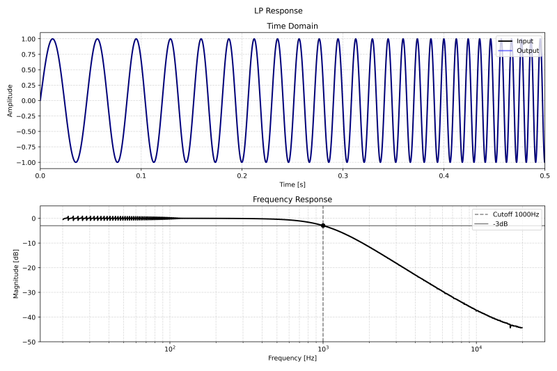
Delta-Sigma DAC#
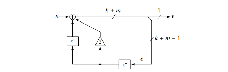
The delta_sigma.sv module converts the final 14-bit digital audio into a 1-bit Pulse-Density Modulated (PDM) signal using a second-order error-feedback delta-sigma modulator. The structure was found in Understanding Delta-Sigma Data Converters by Richard Schreier and was chosen due to its simplicity.
Modulator Structure#
The modulator operates at 10 MHz for an Oversampling Rate (OSR) of 200 and uses error feedback:
$$ y[n] = x[n] + 2 \cdot e_1[n-1] - e_2[n-1] $$Where \(e_1\) and \(e_2\) are the first and second-order error terms. The quantiser is simply the sign bit:
- \(y \geq 0 \Rightarrow \text{PDM} = 1\)
- \(y < 0 \Rightarrow \text{PDM} = 0\)
The quantisation error is:
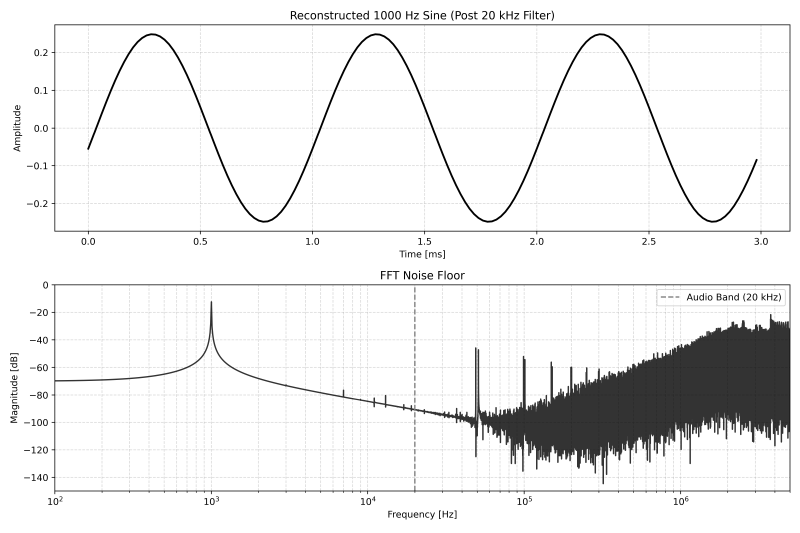
$$ e[n] = y[n] - q[n] $$where \(q[n]\) is +32,768 or −32,768 depending on the PDM output. This error cascades through two integrator stages, shaping the noise spectrum to push quantisation noise above the audio band.
Noise Shaping & Effective Resolution#
The Signal-to-Noise Ratio (SNR) is given by:
$$ \text{SNR} \approx 6.02N + 1.76 + (2L + 1) \cdot 10 \cdot \log_{10}(\text{OSR}) $$where \(N = 1\) (1-bit quantiser) and \(L = 2\) (second-order). This yields a SNR of ~76 dB, or ~12 bits.
Input Scaling#
To best maximize the range of the Delta-Sigma modulator, and to achieve the best possible SNR, the audio input is scaled by 16x. Consider the case of a single voice being active at maximum amplitude, the incoming 10-bit waveform has peaks at 511. With a scaling factor of 16x, the amplitude (normalized to a maximum of 1):
$$ A = \frac{511 \cdot 16}{2^{15}} \approx 0.25 $$The absolute worst case is three identical, maximum amplitude waveforms arriving at once. The resulting amplitude is 0.75, which is towards the limits of the modulator can faithfully produce. If the filter were then active with a high enough Q, the amplitude could saturate the modulator. In this case, the global volume can tune the signal down to acceptable levels.
Reconstruction#
The PDM output must be passed through an external low-pass filter to recover the analog audio signal. Since the modulator is 2nd order, the noise will rise with 40dB/dec at higher frequencies, thus at least a 3rd order filter is needed. During testing with Python, I found a 4th order Bessel filter to sound the best.
Verification & Simulation#
The TT6581 project has two verification environments:
- Verilator C++ testbenches: Super fast. Used for development and iteration. The speed allows simulating hundreds of seconds.
- CocoTB Python testbenches: For regression and gate-level validation.
Verilator Testbenches#
All Verilator testbenches are in sim/ and run with make <target>:
| Target | Description | Output |
|---|---|---|
tt6581 | 10-second demo song using all features | .wav |
tt6581_player | Full Monty on the Run (360s) | .wav |
tt6581_bode | Sine sweep | Plot |
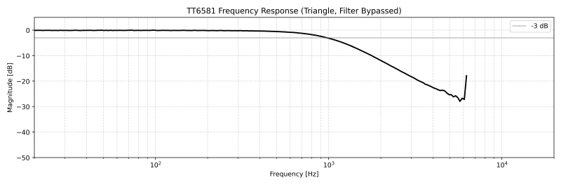
svf | SVF frequency response (all 4 modes) | Plot |
envelope | ADSR envelope capture | Plot |
delta_sigma | Sine input to Delta-Sigma. Waveform reconstruction and PDM frequency spectrum | Plot |
mult | Multiplier randomised test | Pass/Fail |
spi | SPI read/write test | Pass/Fail |
Demo Song (sim_tt6581.cpp)#
A 10-second composition programmed directly in C++ that exercises all three voices, multiple waveform types, ADSR envelopes, arpeggios, and filter sweeps. Voice 1 plays a pulse-wave lead melody, Voice 2 provides a sawtooth bass line, and Voice 3 runs triangle arpeggios. The filter sweeps from 600 Hz to 8 kHz low-pass across the piece, switching to high-pass for the final fade-out.
SID Player (sim_tt6581_player.cpp)#
This testbench was the major goal of the project: playing entire SID songs through the actual RTL design. The stimulus files are generated by:
- Running the original 6502 assembly code (from this repository) in a modified 6502 emulator
- Recording all memory writes to the SID address range
- Translating the captured register writes to TT6581 addresses
These register dumps are then fed into the Verilator simulation, which runs the full TT6581 RTL. The 1-bit PDM output stream produced by the simulated design is captured and reconstructed into audio through the Bessel filter pipeline. The following MP3s are direct recordings from the RTL testbench output. No post-processing other than the reconstruction filter:
Monty on the Run - Rob Hubbard
Cybernoid II - Jeroen Tel
Commando - Rob Hubbard
Bode Plot (sim_tt6581_bode.cpp)#
Measures the frequency response of the entire TT6581. A triangle wave is swept from low to max frequency wiht a 1 kHz low-pass filter enabled. A python script reconstructs the audio from the PDM and computes a per-frequency amplitude levels.
CocoTB Tests#
Three Python-based tests run as GitHub Actions on every push. These tests are performed against both the RTL and the synthesised gate-level netlist. The results from these testbenches are shown as a summary on the action along with a short description. Results are available on the project’s GitHub Actions:
References#
- Musical Applications of Microprocessors - Hal Chamberlin. Source for the Chamberlin State-Variable Filter topology.
- Understanding Delta-Sigma Data Converters - Richard Schreier, Gabor C. Temes. Source for the error-feedback delta-sigma modulator design.
- MOS6581 Datasheet - Original SID chip reference.
- Tiny Tapeout - The open-source ASIC platform used to fabricate the TT6581.